From Concept to Cure: Mastering Liquid Silicone Rubber for Medical Device Design
23 January 2024
Liquid silicone rubber (LSR) is frequently used in implants due to its bio-inert nature, meaning that it has a very low propensity to initiate a response or interaction when introduced to biological tissue.(1) It is also a common choice in non-implantable drug delivery devices, as it lowers development risk when performing the relevant biocompatibility tests recommended in ISO 10993 and US Pharmacopeia Class VI. This property also makes LSR suitable for the drug flow path, where reliable performance in extractables and leachables testing is critical. For example, Raumedic provides a range of customised silicone syringe plungers with this as one of its unique selling points.(2)
More than meets the skin
Compared with other elastomers, silicone rubbers have the best compression set performance. Typical values are around 10%–20%,3 compared with other elastomers with compression sets of 40%–70%.4 This makes LSR a more robust choice for seals in devices with a long service and/or shelf life. When comparing different LSR grades, it is important to keep in mind that there are differing standards for compression set testing that can affect the number quoted on the datasheet. Different additives, and even manufacturing conditions, can further improve or impair this property – for example, self-adhesive grades can exhibit a much higher compression set of 40%–60%.5
All rubbers typically exhibit high friction, with coefficients of around 0.5–1.0. However, LSR is likely to be a suitable choice when compared with its peers if a complex dynamic seal is required while avoiding any additional coating processes. Harder silicones with a higher durometer score typically exhibit a lower coefficient of friction, however, their decreased compliance results in a smaller tolerance window for effective sealing and friction forces. The surface finish of both sealing surfaces is also extremely important, where more polished surfaces can increase the coefficient significantly. Finally, the friction performance of similar grades from different manufacturers can vary, so it is advisable to carry out functional testing with a range of options to maximise the chance of design success. Most LSR suppliers provide a range of low-friction LSR grades, however the coefficients of friction are usually not quoted. It is therefore prudent to be sceptical of any marketing claims, especially if grades have contradictory attributes such as “low friction” and “self-adhesive”.
Two-shot (2K) LSR over moulding is a common operation in the world of silicone. The most advanced high-volume systems use a rotating table with parallel substrate and LSR injections to increase throughput. Automated pick and place systems are also used at lower volumes and, at the prototyping stage, the moulder will do this manually. Part design requires some care, where any high-contact-force dynamic seals may also require mechanical interlocking features to back up any chemical adhesion that comes from using a primer or self-adhesive grade. Typical materials to pair with LSR include polybutylene terephthalate (PBT), polyamide (PA), polycarbonate (PC) and polyethylene terephthalate (PET).
Despite its propensity to crosslink and slightly harden, platinum-cured LSR is compatible with gamma or X-ray sterilisation. At industry-standard radiation doses of 25 kGy, Gautriaud et al noted an increase of the shore hardness of Wacker’s (Munich, Germany) Elastosil® 3003/50 by four points, as seen in Figure 1.6,7 If this increase is accounted for in the design phase, it is possible to employ this method for end-of-line sterilisation to reach any surfaces that are sealed away.
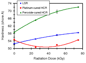
Figure 1: Effect of gamma radiation on durometer hardness of silicone rubbers.(7)
The LSR process is a bit different
LSR is typically supplied as A and B components in pails, mixed in a 50:50 ratio at room temperature and then pushed into a hot mould tool. Tool temperatures of around 200°C allow curing times in the order of seconds. A longer cure time at lower temperatures may be used at the prototyping stage without a drop in part quality.
Note that the properties, such as the viscosity, of the mixed A and B components can vary significantly between different material grades, which can end up causing unforeseen headaches for a moulder trying to use the same equipment over a range of grades. Additionally, the flowability of the mixed components can affect the expected tolerance ranges of any surfaces.
The tolerance of an LSR part is highly dependent on the manufacturer of the tool and the design of the part. Typically, shrink rates are high but consistent throughout the part. As long as the LSR is unconstrained during shrinking, a quality tool can produce LSR parts accurately. Walls as thin as 0.25 mm are possible, but the flipside of this is that LSR will flash very easily. If possible, move any parting lines and ejector pins away from sealing surfaces to minimise the chance of leakage.
Even large contract manufacturers are unlikely to have professional LSR moulding machines, leaving the practice to specialists like Trelleborg (Trelleborg, Sweden) or Raumedic. However, with the right partner, accurate prototypes can be made using a pump and heated tool that is opened and shut manually. An example of this set-up is shown in Figure 2.
Manufacturers only familiar with mechanical probe-based co-ordinate measuring machines (CMMs) may also struggle to measure the part. A brief summary of measurement methods for LSR can be found in Table 1.
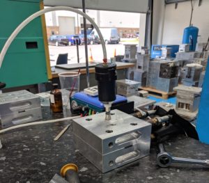
Figure 2: Manual LSR mould tool for low-volume prototype components.
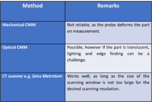
Table 1: Measurement methods for LSR.
Hyperelastic finite element analysis
Finite element analysis (FEA) of rubber components is a common point of discussion, due to the difficulty and amount of up-front investment required to prototype them. For medical device engineers, an FEA model also provides the ability to try a variety of dimensions across the tolerance ranges and map the contact pressures along the seal. This helps to build confidence that the design will be robust to sigma level six or “five nines”.
A “gold standard” FEA model would start with a set of the following material tests,8 ranked in order of importance:
- An equibiaxial tension test – as LSR is nearly incompressible, this creates a loading state equivalent to pure compression, without the friction that would be impossible to avoid with a simple compression test
- A planar tension test (pure shear) – also due to the LSR being nearly incompressible, using a wide sample creates a state of pure shear at a 45° angle.
- A simple tension test.
The results of these tests can then be curve-fitted against different material models, such as Mooney-Rivlin, Neo-Hookean, Arruda-Boyce, Ogden or Yeoh. The curve with the best fit is then selected for use with the final FEA model.
The problem with the “gold standard” approach is that engineers are unlikely to know exactly which material grade is the most preferable at the outset. Also, material suppliers are unlikely to share data for niche material test methods, so performing these tests requires extra investment. As a first pass, it is possible to use a set of Mooney-Rivlin parameters for hyperelastic materials shared across the FEA community,9,10 which have been found to be good enough when trying different concept designs and material shore hardnesses. If there is still a desire to revisit the FEA for design optimisation before tooling, the material tests can be conducted with the selected grade to confirm the result and conduct any optimisation tweaks.
A demonstration of a hyperelastic FEA model is shown in Figures 3 and 4, where Figure 3 shows the assembly of two components which are sealed by an LSR O-ring, and Figure 4 shows the effect of pressurisation from the top side. The surface stress at the sealing faces is equivalent to the contact pressure, which can be used to determine the integrity of the seal. Conducting hyperelastic FEA requires a skilled operator with an understanding of common pitfalls in model set-up – for example, meshing producing artefacts, such as hourglassing, during the solve.
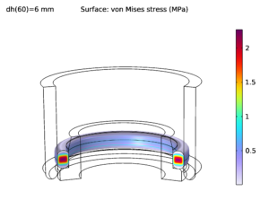
Figure 3: Hyperelastic FEA model of the assembly of two components and an LSR O-ring.
Gauging real-world performance
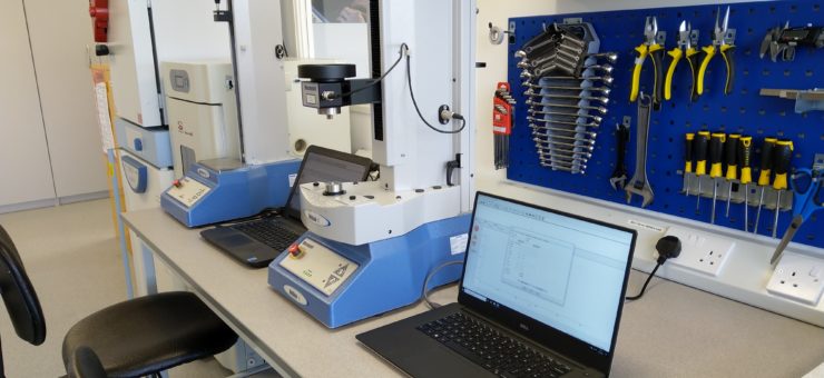
A full suite of mechanical testing equipment is required to test LSR components, some examples of which are shown in Figure 5. Force testers are extremely useful for running long-term seal compression tests in parallel. A torque tester can be indispensable for the testing of dynamic rubber seals driven by a motor or clock spring.
For medical device designers, any statistical analysis must be robust against the tough requirements set by regulators. This is especially relevant when producing components that seal, where tolerance stacks must be tightly controlled to ensure that there is adequate contact pressure for effective fluid retention.
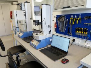
Figure 5: Mecmesin (Horsham, UK) force and torque testers.
Summary
In summary, LSR is a unique and useful material with excellent biocompatibility, compression set and friction properties without additives. The LSR moulding process differs significantly from standard injection moulding, and therefore requires a specific skillset and experience to design for, model and manufacture effectively.
If you are working on a device with a critical compliant seal and need to make important design decisions, or if you have any general questions in this area, please feel free to contact us to find out how we can help.
References
- Rao HM et al, “Bioinert and Bioactive Materials – Narrative Review”. J Pharm Negat, 2022, Vol 13(Special Issue 7), pp 2251–2255.
- “Customized silicone syringe plungers by Raumedic”. Web page, Raumedic, accessed Jan 2024.
- Bayerl H, “Compression Set of Silicone Elastomers”. Int Ploym Sci Technol, 2009, Vol 36(8), pp 1–4.
- “TPE with Optimised Compression Set”. Web page, HEXPOL, accessed Jan 2024.
- “ELASTOSIL®”. Web page, Wacker, accessed Jan 2024.
- “The use of Ionising Radiation in the Manufacture of Medicinal Products”. EMA Guidance, 1991.
- Gautriaud E et al, “Effect of Sterilization on the Mechanical Properties of Silicone Rubbers”. BioProcess International, Apr 2010.
- “Elastomer (hyperelastic) Characterization”. Web page, Axel Physical Testing Services, accessed Jan 2024.
- Altidis P, Warner B, “Analyzing Hyperelastic Materials w/ Some Practical Considerations”. Presentation, Midwest ANSYS Users Group, May 2005.
- Lalo DF, Greco M, “Rubber bushing hyperelastic behavior based on shore hardness and uniaxial extension”. 24th ABCM International Congress of Mechanical Engineering Conference, Dec 2017.